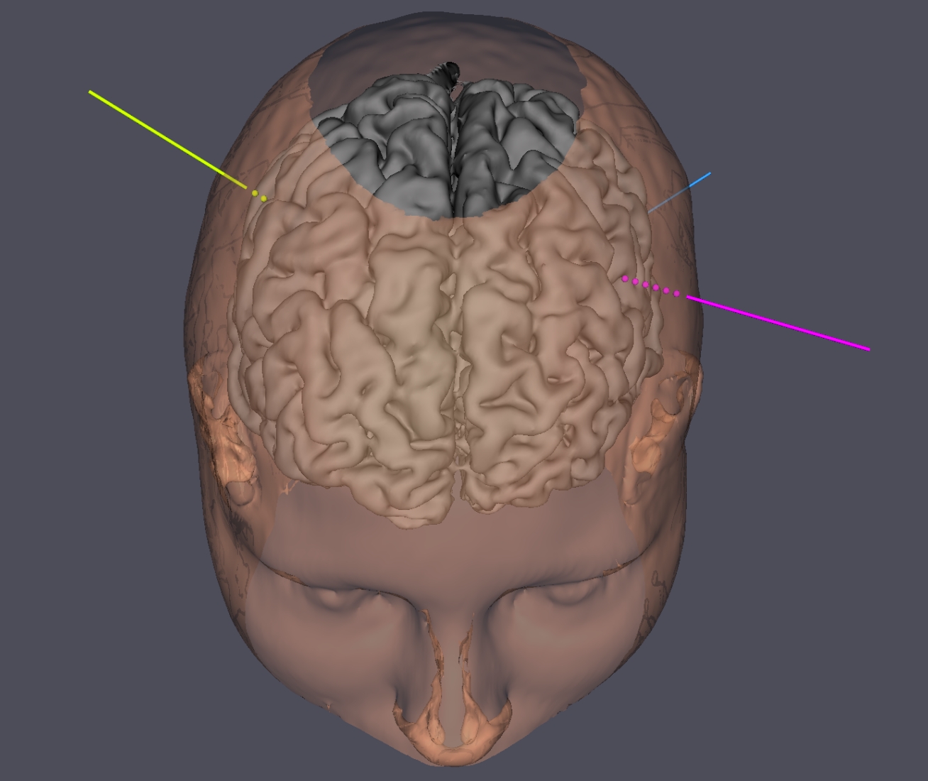
The Jimbo software is able to create 3D volume renderings from MRI or CT-scan slices (see example above).
These algorithms are available:
- A density algorithm to create a surface from a uniform density area (see “How to use the
- An algorithm to extract the gray matter of the brain from an MRI performed on T1-weighted images (see “How to use the brain extractor algorithm ?”),
- A basic algorithm for extracting vessels (see “how to use the extracting vessels algorithm ?”).
Planes can be extracted from the DICOM volume and displayed on the 3D scene, using the tab “Display extracted slices and depth electrodes”.
When the user press the left button of the mouse, the cutting tool is represented at the surface of the 3D object. When the left button is released, the intersection between the 3D object and the cutting tool is erased.
The size of the cutting tool can be selected in the spinbox. Default value is 4 mm.
The program stores the last 10 changes in the 3D object as the cutting tool is selected. When the cutting tool is unselected, the changes are no more available.
To reverse the last ten changes, press the icon representing a back arrow . To go forward, press the forward arrow .
The cutting tool is associated with an algorithm that keeps only the largest part of the 3D object. Thus, when the cutting operation is finished, the remaining individual elements of the 3D object, generated by the cutting operation, are automatically deleted.
The user can draw a colored circle on the 3D object. The principle of the drawing tool is similar to the cutting tool. When the user press the left button of the mouse, a sphere is represented at the surface of the 3D object. When the left button is released, the intersection between the 3D object and the drawing tool is colored in blue. This color can be changed in a second step using the “list of 3D actors” which is displayed in the “tools for volume rendering” window. A double click on the color cell will display a color dialog window in which a new color can be selected.
By default, the size of the color tool is 4 mm. As for the cutting tool, this size can be changed using the spinbox.
The ten last paintings on the 3D object can be reversed using the backward or the forward tools.
The default background color of the 3D scene is black. It can be modified using the background color icon.
When the user press this icon, a dialog color window is displayed. A new background color can be selected.
The user can export the 3D scene under the VRML 2.0 format (Virtual Reality Modeling Language).
The color, name, position of the 3D actors are stored in this format. The VRML file can be read by other software.The location of the VRML 2.0 file on the disk is shown in a dialog box.
The user can import the 3D scene which was previously recorded. The list of the 3D actors is automatically updated according to the actors stored in the VMRL 2.0 file. These actors can then be modified (color, transparency, name…) or eraser. The user can add some new 3D objects and then re-export the whole scene.
The location of the VRML 2.0 file on the disk is shown in a dialog box.
JimboDICOMViewer
User’s manual apr-2015